29 Bridges Built Before Modern Engineering Rules
Before standardized load ratings, safety factors, and material testing became codified requirements, bridge builders relied on accumulated experience, trial and error, and a willingness to over-build rather than calculate precisely. Many of the structural types on this list predate the engineering codes that would eventually govern how much weight a bridge could carry, how wide its lanes needed to be, or how it had to be inspected over its lifetime.
What makes these types worth understanding is not just their age but the sheer variety of problem-solving they represent, developed independently across different regions and eras before any shared international standard existed to guide the work. Several of these construction methods remain visible today only in surviving, carefully preserved examples.
Covered Wooden Bridges
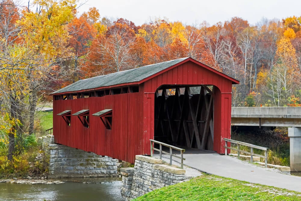
Enclosed with a roof and siding not for decoration but to protect the structural wooden trusses beneath from weather exposure, covered bridges could last many decades longer than an equivalent uncovered wooden span. Builders relied on wooden peg joinery and hand-cut timber framing techniques passed down through carpentry trades rather than formal engineering calculation.
The roof and siding added significant weight of their own, which builders accounted for through experience-based proportioning rather than any standardized load formula.
Dry-Stone Arch Bridges
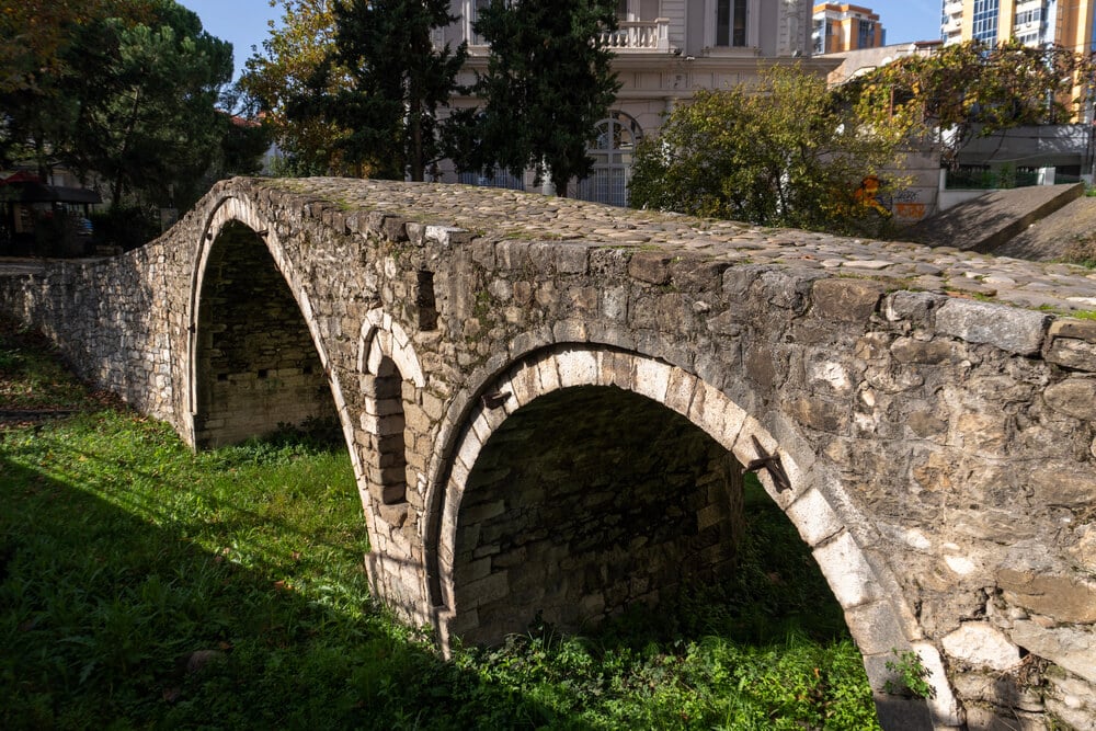
Built entirely without mortar, relying instead on precisely cut and fitted stone blocks held in compression by the arch’s own geometry, dry-stone arch construction depended almost entirely on the skill of individual stonemasons rather than any documented engineering standard. The arch shape itself, rather than any binding material, provided the structural integrity, with weight transferring outward and downward through the stones toward the abutments at either end.
Many surviving examples have stood for centuries with only minimal maintenance beyond periodic repointing of loosened stones.
Clapper Bridges
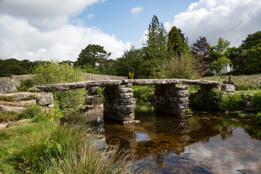
Among the simplest bridge forms, clapper bridges consist of large flat stone slabs laid directly across stone piers with no arch or mortar involved at all. Their construction required no calculation beyond selecting a slab long and thick enough to span the gap without cracking under expected foot or animal traffic.
Surviving examples are typically found on smaller waterways, since the flat-slab method could not practically span wider crossings.
Packhorse Bridges
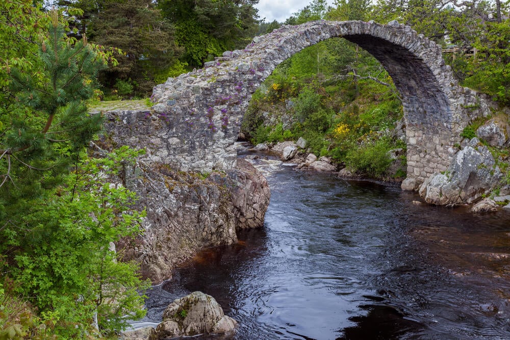
Narrow stone bridges built specifically for foot and animal traffic rather than wheeled vehicles, packhorse bridges typically featured low parapets or none at all, allowing the wide loads carried by pack animals to clear the bridge’s edges without obstruction. Builders sized the narrow width based purely on the practical needs of loaded pack animals rather than any standardized traffic width.
Many of these bridges predate wheeled vehicle traffic on the routes they served entirely.
Humpback Bridges
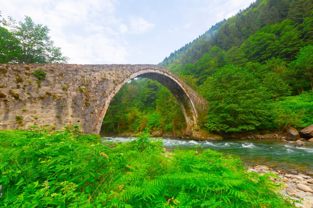
Featuring a pronounced upward arch in the roadway itself rather than a flat deck, humpback bridges allowed builders to achieve greater clearance over a waterway using a shorter overall span than a flatter design would have required. The steep grade created by the hump was accepted as a practical tradeoff long before any standard governed maximum acceptable road gradient on a bridge.
This design became increasingly impractical as vehicle speeds increased, leading many surviving examples to be restricted to pedestrian use only.
Medieval Bridges With Shops and Houses
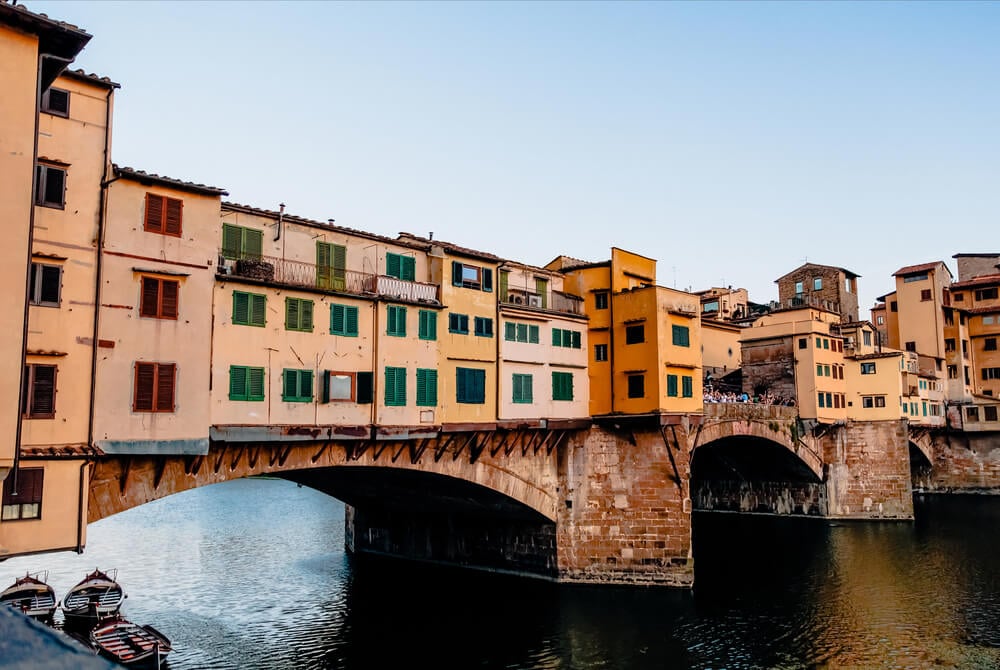
Certain medieval stone bridges were built wide enough to support entire rows of shops, houses, or a chapel constructed directly on the bridge deck itself, effectively functioning as an extension of the town’s commercial street network. The additional weight of these structures was managed through significantly overbuilt stone piers, since no formal method existed at the time to calculate the precise additional load the buildings would add.
Fire was a persistent risk given the density of wooden-framed structures built atop a stone span, and several notable examples were significantly damaged or destroyed by fires over their history.
Roman Segmental Arch Bridges
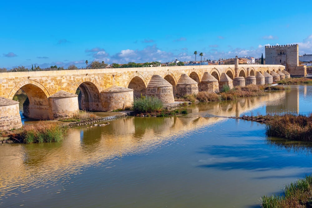
Using arches that span less than a full semicircle, segmental arch construction allowed Roman engineers to achieve longer spans with shallower rises than a full semicircular arch would require, reducing the overall height and material needed for the bridge. Builders relied on standardized construction techniques developed and refined across the empire’s extensive road and aqueduct network, effectively an informal precursor to later formal engineering codes.
Many surviving examples remain in use for pedestrian or light traffic today, nearly two thousand years after original construction.
Cast Iron Arch Bridges
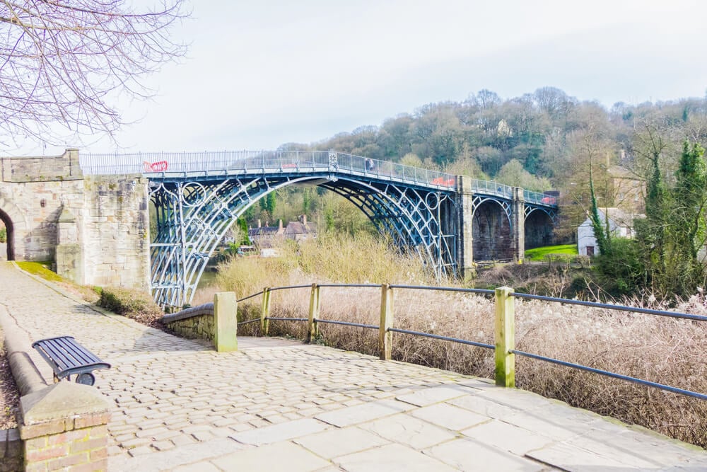
Among the earliest bridges to use iron as the primary structural material rather than stone or timber, cast iron arch construction was pioneered in the late 18th century as ironworking technology matured enough to produce components strong and reliable enough for structural use. Builders had limited prior experience with iron’s specific failure characteristics under tension, leading to conservative, heavily reinforced designs that erred toward excess material rather than precise calculation.
The Iron Bridge at Coalbrookdale in England, completed in 1779, is widely cited as the first major bridge of this type and remains a preserved landmark today.
Wrought Iron Truss Bridges
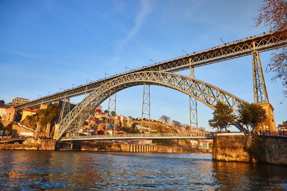
Replacing cast iron’s brittleness under tension with wrought iron’s greater flexibility and tensile strength, wrought iron truss bridges represented a significant material advancement during the 19th century, though still built without the standardized load calculations that would later govern truss design. Builders relied on empirical testing and observed performance of earlier bridges to guide proportions rather than any formal structural analysis method.
Many of these bridges were eventually replaced as steel became the preferred structural material, though surviving examples remain valued for their historical significance.
King Post Truss Bridges
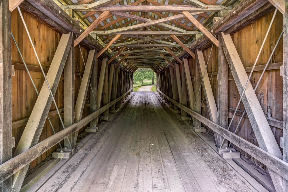
Among the simplest truss designs, a king post truss uses a single vertical post connecting the peak of a triangular frame down to the center of the horizontal beam below, distributing load through basic triangulated geometry. This design’s simplicity meant it required minimal specialized engineering knowledge to construct correctly, making it accessible to local builders without formal training.
Its structural limitations meant it was generally reserved for shorter spans rather than larger crossings.
Queen Post Truss Bridges
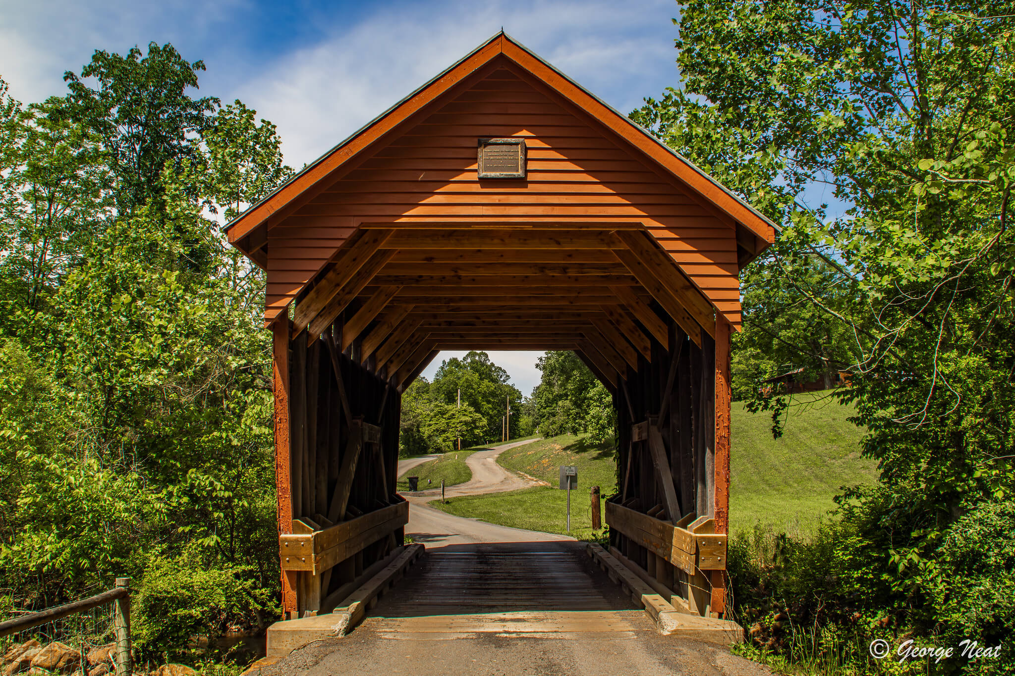
An extension of the king post design using two vertical posts rather than one, connected by a horizontal beam at the top, queen post trusses could span somewhat greater distances than a king post design while still relying on relatively simple, empirically understood geometry. Like the king post truss, this design was widely accessible to builders without formal engineering training, contributing to its widespread use on smaller rural crossings.
Many surviving covered bridges use this truss type specifically due to its balance of simplicity and span capability.
Burr Arch Truss Bridges
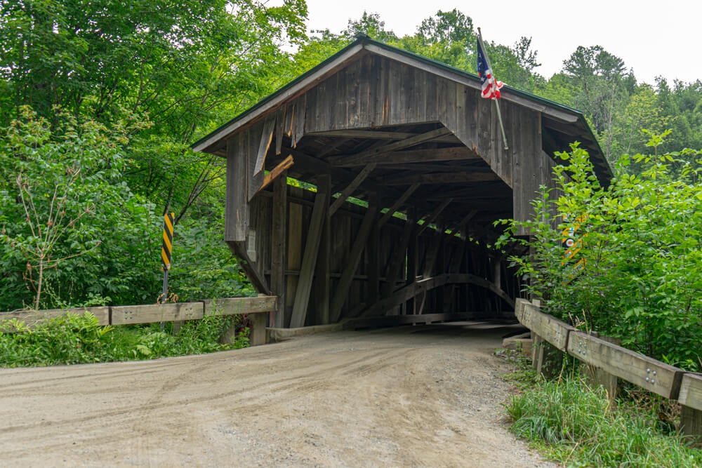
Combining a wooden arch with a conventional truss framework, the Burr arch design distributed load through both the arch’s compression and the truss’s triangulated framework simultaneously, offering greater span capability and strength than either method alone. This hybrid approach was developed through practical innovation and refinement by individual builders rather than any centralized engineering standard.
The design remains closely associated with 19th-century covered bridge construction in particular.
Town Lattice Truss Bridges
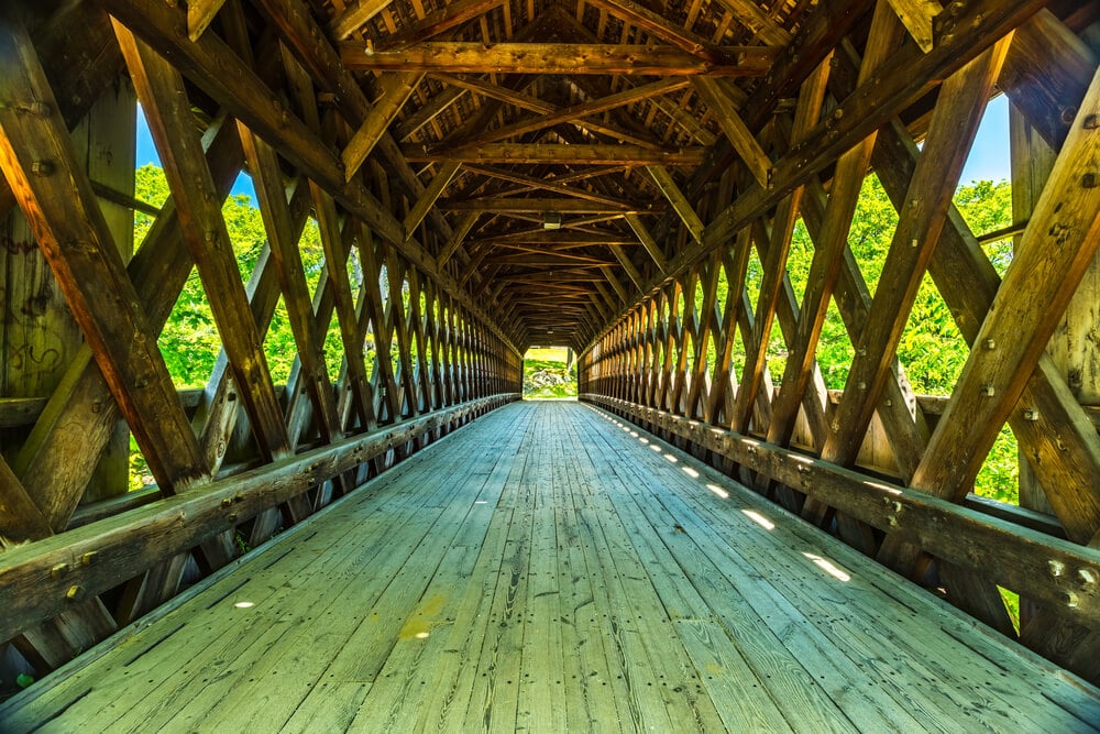
Using a dense, repeating diagonal lattice pattern of relatively light timber members rather than a small number of heavy structural beams, the Town lattice truss was specifically designed to be buildable by less specialized labor using standardized, interchangeable wooden components. This approach represented an early move toward a more systematized construction method, even without the formal calculation-based codes that would later govern truss design broadly.
Its patent and promotion by its original developer helped standardize the design’s use across a wide geographic area during the 19th century.
Howe Truss Bridges
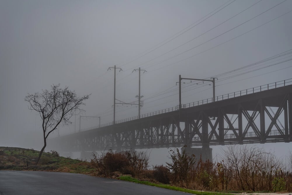
Incorporating iron vertical rods in combination with wooden diagonal members, the Howe truss represented an important transitional design between fully wooden and fully metal truss construction. The iron rods could be tightened using turnbuckles to adjust tension after construction, an innovation that gave builders a practical way to fine-tune a structure’s performance without formal calculation.
This adjustability made the design popular for both bridges and, later, roof truss construction in buildings.
Pratt Truss Bridges
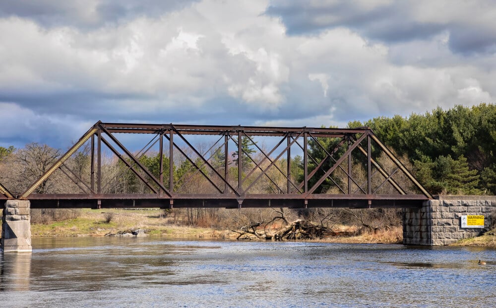
Featuring diagonal members angled to handle tension while vertical members handled compression, the Pratt truss design proved particularly well suited to iron and steel construction, since those materials handled tension loads more efficiently than wood. Early examples were built well before formal structural codes standardized exactly how such a truss should be proportioned for a given span and expected load.
The design’s efficient use of material made it popular for railroad bridges, which demanded significantly greater load capacity than typical road crossings.
Warren Truss Bridges
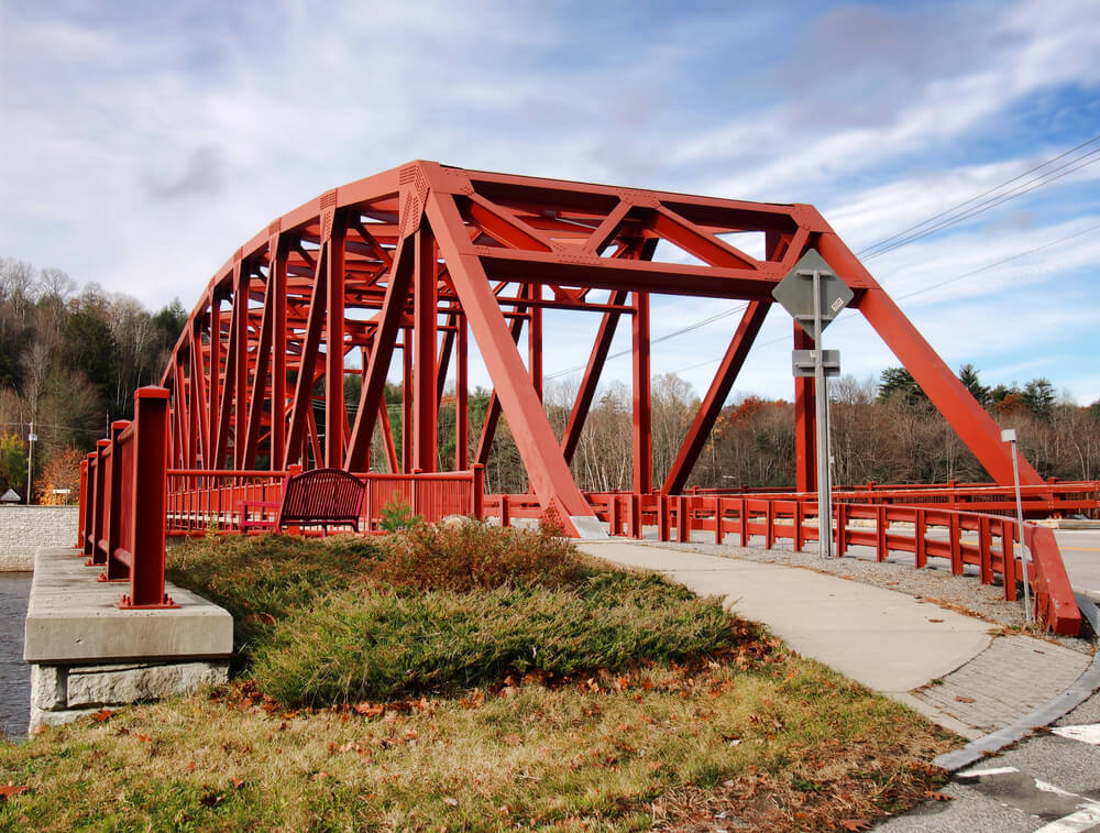
Built from a repeating series of equilateral or isosceles triangles without vertical members in its original form, the Warren truss distributed load through the triangulated diagonal members alone. Early riveted examples were constructed based on the accumulated experience of ironworkers and builders rather than the calculated safety factors that would later become standard.
The design’s relative material efficiency made it a popular choice as steel construction became more widespread through the 19th century.
Bowstring Truss Bridges
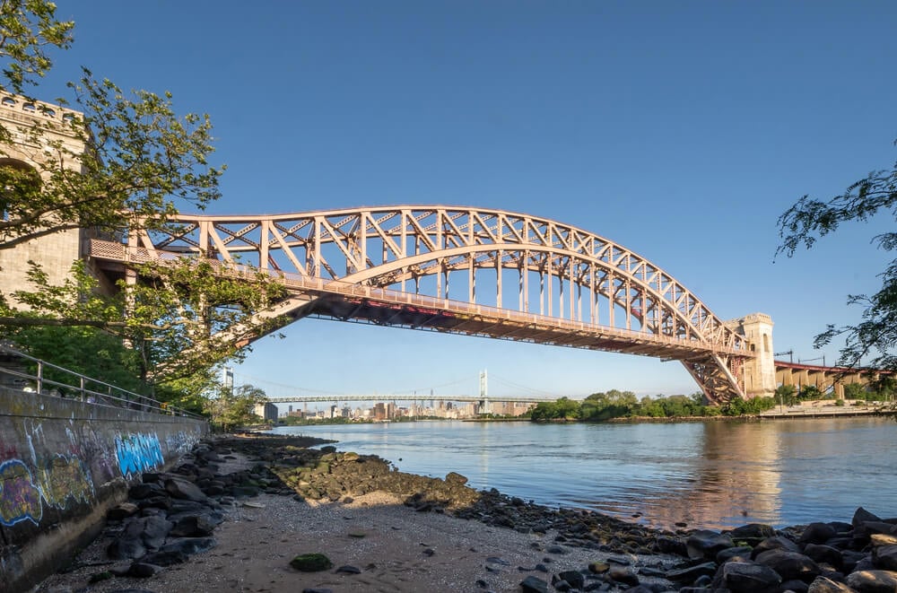
Featuring a curved top chord resembling an archer’s bow paired with a straight bottom chord, bowstring trusses combined arch-like compression behavior with truss-like tension behavior in a single hybrid structure. Builders developed this design through practical iteration, adjusting the curve’s proportions based on observed performance rather than formal calculation.
Cast and wrought iron versions of this design were common in mid-19th-century construction before steel became the dominant structural material.
Whipple Truss Bridges
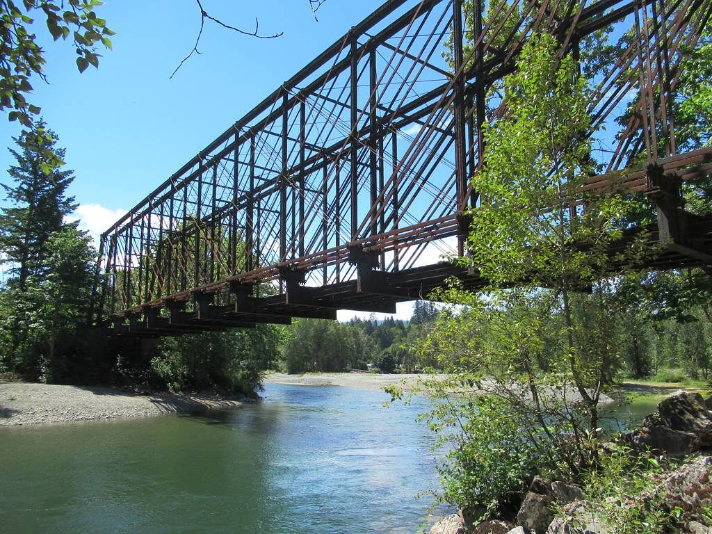
Distinguished by diagonal members that span two panels of the truss rather than one, the Whipple truss allowed for longer overall spans than simpler truss patterns of the same era. Its more complex geometry required a somewhat more sophisticated understanding of load distribution than simpler truss types, even though it still predated formal structural engineering codes.
This design saw significant use on early railroad bridges, which required the greater span capability it offered.
Lenticular Truss Bridges
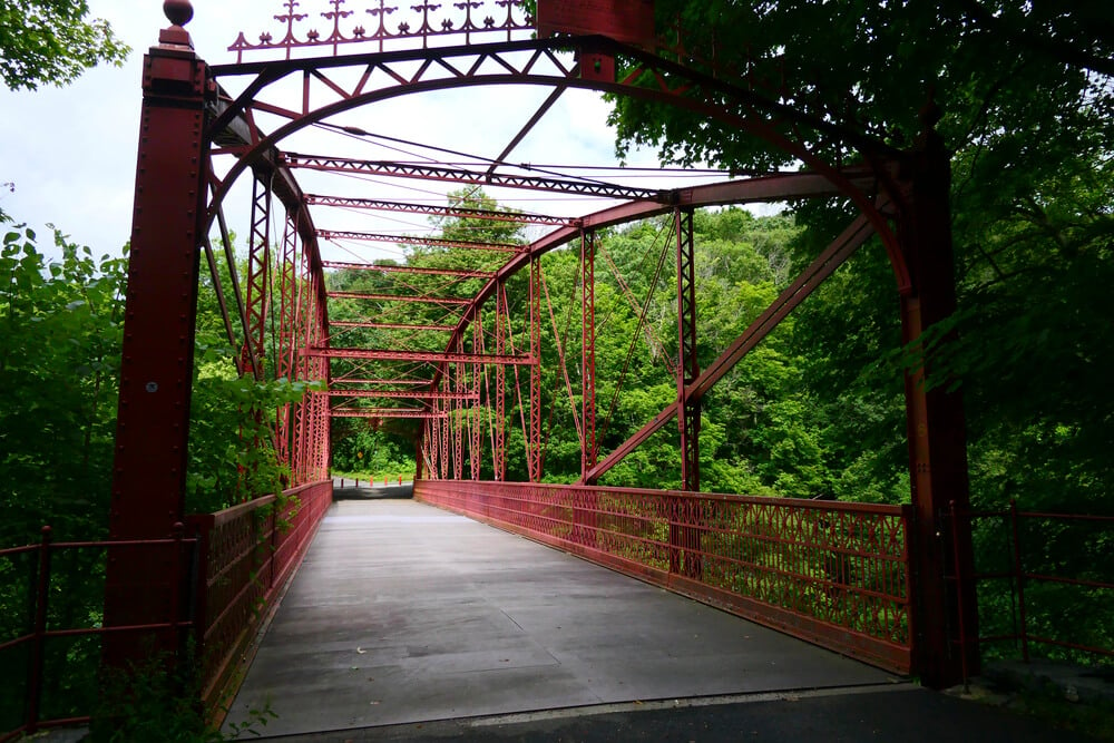
Featuring both a curved top chord and a curved bottom chord that together create a lens-like profile when viewed from the side, lenticular trusses were developed as a way to more efficiently distribute stress across a span compared to straight-chord truss designs. This design required more sophisticated iron and steel fabrication techniques to achieve the curved chord shapes accurately.
Surviving examples are relatively uncommon today compared to more standard truss patterns, making preserved lenticular bridges a particular focus for historic bridge preservation efforts.
Swing Bridges
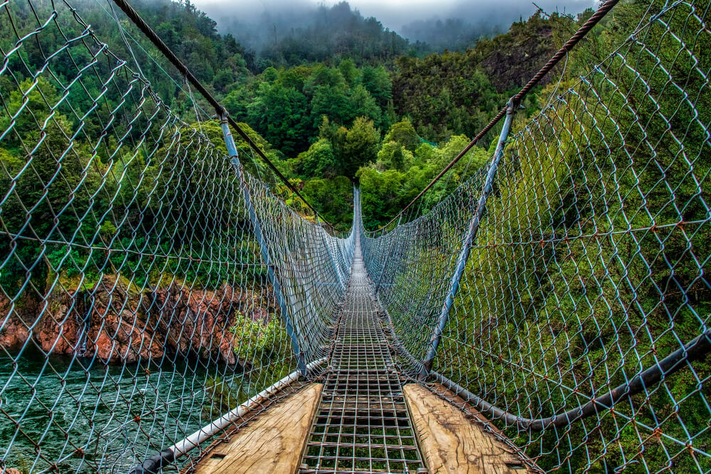
Designed to pivot horizontally around a central pier, swing bridges allowed river or canal traffic to pass through an open channel when the bridge was rotated out of the way, a mechanical solution to navigation conflicts that predated the more complex lifting and folding bridge designs that came later. The pivoting mechanism itself required careful mechanical engineering, even in an era before formal structural codes governed the surrounding bridge deck construction.
Many swing bridges required a dedicated operator to manually manage the rotation mechanism for each vessel passage.
Transporter Bridges
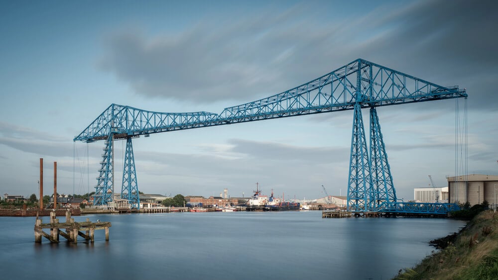
Using a high, fixed overhead structure to support a moving carriage or gondola that ferried vehicles and pedestrians across a waterway without a conventional deck at water level, transporter bridges solved the specific problem of crossing a busy shipping channel without obstructing tall vessel traffic below. This unusual design saw limited but notable use, primarily in the late 19th and early 20th centuries, before falling out of favor as more conventional high-level bridges became more practical to build.
Surviving examples are relatively rare and are typically preserved specifically as significant engineering landmarks.
Suspension Chain Bridges

Predating the wire cable suspension systems used in later, larger suspension bridges, early suspension designs used wrought iron chains made from individually forged links to support the deck below. Builders had to rely on the tested strength of individual chain links rather than the more uniform, calculated strength of later wire cable systems.
Several early chain suspension bridges suffered notable failures, which contributed directly to the gradual development of more rigorous engineering standards for suspension bridge design going forward.
Rope Suspension Footbridges
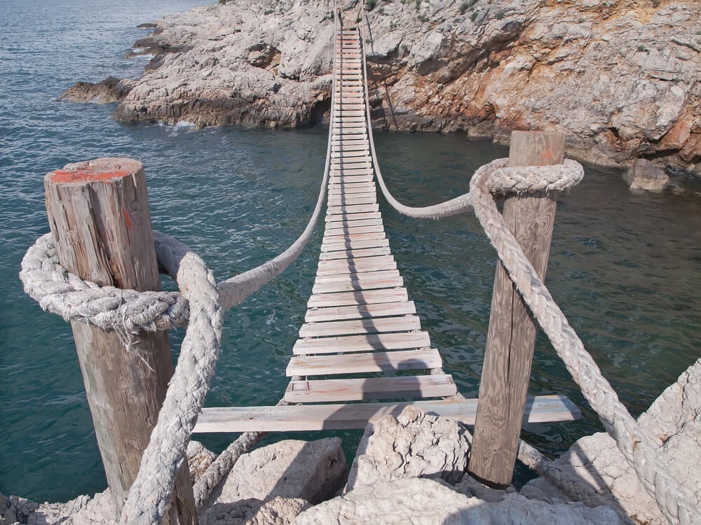
Among the oldest bridge forms still in limited traditional use today, rope suspension footbridges rely on twisted or woven fiber ropes anchored at each end to support a simple deck of wooden planks or woven matting. Construction and maintenance knowledge for these bridges was typically passed down through local communities rather than documented in any formal engineering text.
Regular replacement of worn rope components was essential to the bridge’s continued safe use, managed through observed wear rather than any scheduled inspection standard.
Pontoon Bridges
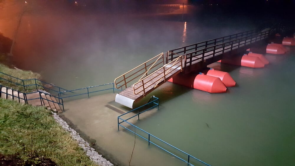
Built from a connected series of floating platforms, historically including anchored boats, timber rafts, or inflated skins, supporting a deck laid across the top, pontoon bridges offered a way to cross a waterway without the time and material investment of a fixed structure. Their temporary or semi-permanent nature meant they were generally built based on immediate practical need and available materials rather than long-term structural planning.
Military forces made extensive historical use of this bridge type specifically for its speed of construction and eventual removal.
Floating Timber Bridges
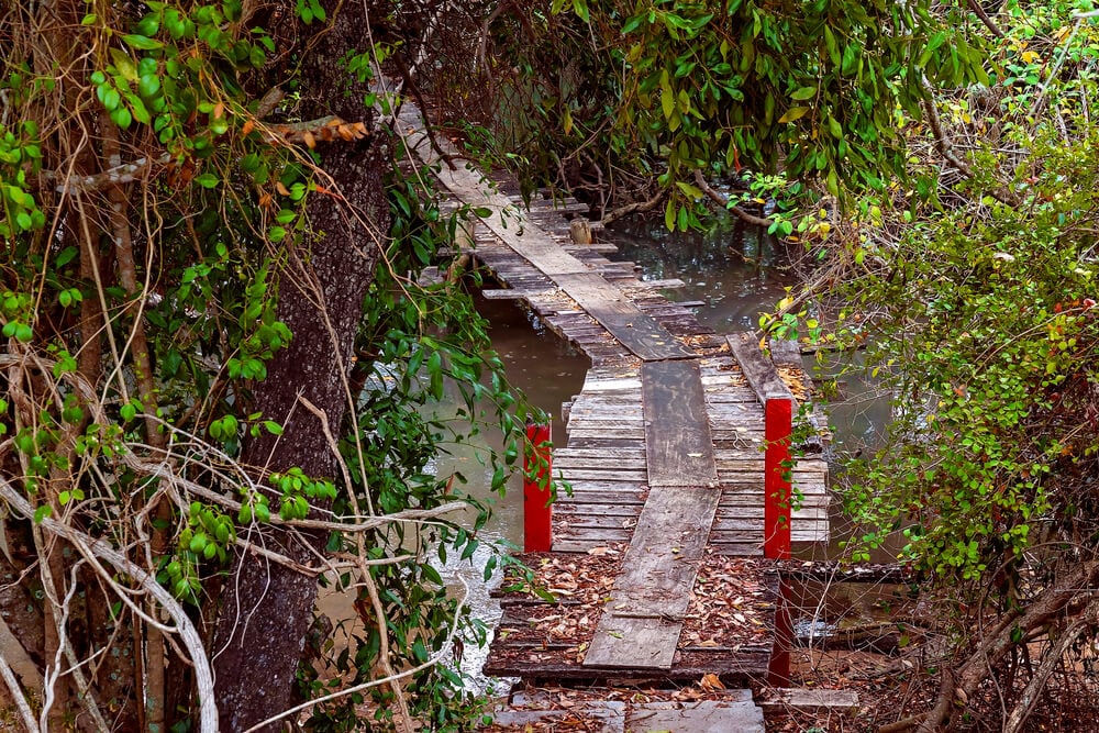
A more permanent variation on the pontoon concept, floating timber bridges used larger, more substantially built wooden platforms secured by anchors or chains to remain in a fixed position despite resting on the water’s surface rather than fixed piers. Builders had to account for water level fluctuations and current forces through practical, observed adjustment rather than calculated hydraulic engineering.
These bridges required more frequent maintenance than fixed structures, given the constant stress of water movement on the floating platform sections.
Tubular Girder Bridges
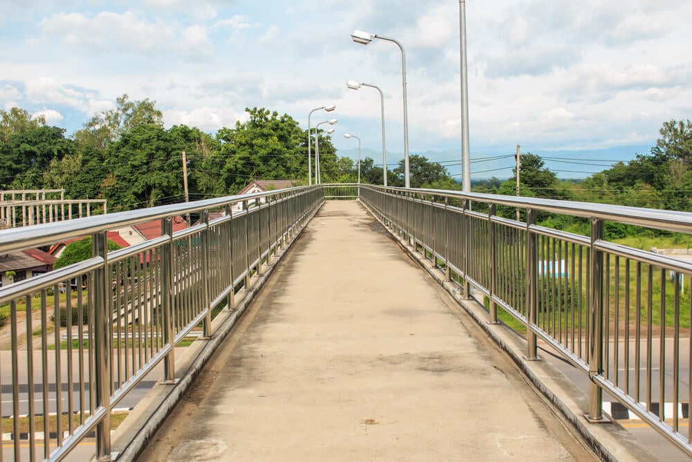
Using a large, hollow rectangular or oval iron tube through which trains or vehicles actually traveled, rather than a truss or arch supporting an open deck, tubular girder construction represented a distinctive and structurally unusual mid-19th-century engineering approach. Builders conducted extensive physical testing on smaller prototype sections to understand the tube’s load behavior, an early example of empirical testing beginning to inform structural decisions before formal calculation-based codes existed.
This design saw limited adoption compared to more conventional truss and arch bridges of the same era, in part due to its significant material cost.
Early Cantilever Truss Bridges
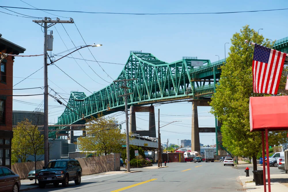
Extending structural members outward from a central support without any support from below at the extended end, early cantilever designs allowed builders to span long distances, particularly over deep water or gorges where building intermediate piers was impractical. Builders relied on careful, if informal, balancing of the cantilevered sections against anchored counterweights on the opposite side of each support.
This design’s inherent complexity meant that early examples were built with considerable margins of extra strength precisely because no formal method yet existed to calculate the exact loads involved with confidence.
Corbel Arch Bridges
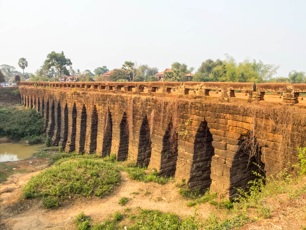
Built by progressively overlapping stone or brick courses inward from each side until they met at the top, corbel arch construction is structurally distinct from a true arch, since it relies on the overlapping stones’ weight and friction rather than the compression forces of a true curved arch. This technique predates true arch construction in many regions and represents one of the earliest methods humans developed for spanning a gap with unreinforced masonry.
Surviving examples tend to be limited to shorter spans, since the technique becomes structurally inefficient at greater widths.
Ice Bridges and Seasonal Crossings
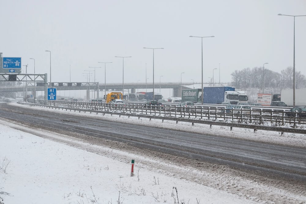
Not permanent structures at all but naturally forming or deliberately reinforced ice crossings over frozen rivers and lakes, seasonal ice bridges allowed regular travel across a waterway during winter months in regions where no permanent bridge existed. Communities relying on these crossings developed informal but often quite precise local knowledge of ice thickness and safe loading limits, effectively an oral tradition of engineering judgment passed between generations.
This practice has become significantly less common as permanent bridge infrastructure has expanded into previously remote regions.
What Experience Taught Before Codes Did

Long before an engineer could run a calculation confirming a bridge’s exact safety margin, builders relied on something closer to inherited memory: which designs had stood for generations, which had failed and why, and how much extra material seemed to buy a reasonable margin of safety. That knowledge was real, even if it was never written down as a formal standard, and it produced structures that in many cases have genuinely outlasted some of what came after them.
The formal engineering codes that eventually emerged did not appear from nowhere. They were built, quite directly, from the documented failures of exactly the kinds of bridges on this list, each collapse or crack a data point in an unplanned, centuries-long experiment that modern engineering now takes for granted.
What survives today from that earlier era stands as proof that careful observation, even without calculation, could still produce something built to last.
More from Go2Tutors!

- The Romanov Crown Jewels and Their Tragic Fate
- 13 Historical Mysteries That Science Still Can’t Solve
- Famous Hoaxes That Fooled the World for Years
- 15 Child Stars with Tragic Adult Lives
- 16 Famous Jewelry Pieces in History
Like Go2Tutors’s content? Follow us on MSN.